Welcome to the RISA-Tekla Link General Reference manual. Please read this topic and pay particular attention to the License Agreement. If you are a first time user of the RISA-Tekla Link it would be beneficial to browse through this manual to become familiar with the interface and capabilities.
The RISA-Tekla Link allows Tekla Structures users to be able to interact with RISA-3D and RISAConnection to get engineering calculations for members and connections. The capability between the two programs (RISA-3D and RISAConnection) is a separate path that is laid out below.
The interface allows you to directly call up RISAConnection once you have your Tekla Structures model fully detailed and complete with connection loads. RISAConnection can then be used to adjust the connection as necessary to get a connection that passes all code prescribed checks. From there you can have the Tekla Structures model automatically update the connections .
Please see the Tekla Structures to RISAConnection Procedure topic for more details on how the RISA-Tekla Link works with RISAConnection.
It is possible to either export a model from Tekla Structures to RISA-3D, or import a RISA-3D model into Tekla Structures. The Tekla Structures interface generates the analysis model and it is that analysis model which can then be exported to RISA-3D. For the import from RISA-3D you simply create a blank Tekla Structures model and import a RISA-3D model into Tekla Structures. Use the same Tekla Analysis Model and RISA-3D file for round-tripping between programs.
Please see the Tekla Structures and RISA-3D Procedure topic for more details on how the RISA-Tekla Link works with RISA-3D.
When the RISA-Tekla Link is installed many of the components are added to the specific user account who installs the link. Thus, the link may not work if someone who is not using the link is the one who installs it.
If you run into this problem we have a utility to make this work called the SetupToolbar.exe. This utility is located in the RISA\RISA Tekla Link\ Utility folder. Just run this (noting that nothing appears to happen) and then start up Tekla Structures and you should now see the RISA Toolbar.
The RISA-Tekla Link can currently support:
The RISA-Tekla Link does not support the following:
The RISA Tekla Link can currently support the connections in the table below:
| Connection Type | Tekla Structures Component | RISAConnection Description |
|---|---|---|
| Clip Angle Shear | Clip angle (141) | Girder(Column)/Beam Clip Angle Connection |
| End Plate Shear1 | End plate (144) | Girder(Column)/Beam End Plate Connection |
| End Plate Moment1 | " | Column/Beam Extended End Plate Moment Connection |
| End Plate Seismic Moment2 | " | Column/Beam Extended End Plate Moment Connection |
| End Plate Moment1 | " | Column/Beam Flush End Plate Moment Connection |
| " | " | Column/Beam End Plate Moment Connection (Extended on the Tension Side) |
| Shear Tab | Shear plate simple (146) | Girder(Column)/Beam Shear Tab Connection |
| Shear Tab (full depth) | Full depth (184) | Girder/Beam Shear Tab Connection (full depth) |
| Shear Tab Through Plate | Shear plate tube column (189) | Column/Beam Shear Tab Connection where the column is a tube or pipe and the connection is a through plate |
| Flange Plate Moment | Bolted moment connection (134) | Column/Beam Flange Plate Moment |
| Flange Plate Seismic Moment3 | " | " |
| Directly Welded Moment | Column with stiffeners W (182) | Column/Beam Direct Weld Moment Connection |
| Seismic RBS Connections4 | Column with stiffeners W (182) & Dogbone (1) | Column/Beam Direct Weld Moment Seismic Connection |
| Shear and Moment Splices5 | Splice connection (77) | Beam Shear Tab Splice Connection |
| '' | " | Column Shear Tab Splice Connection |
| '' | " | Beam Moment Plate Splice Connection |
| '' | " | Column Moment Plate Splice Connection |
| '' | " | Beam Direct Weld Moment Splice Connection |
| '' | " | Column Direct Weld Moment Splice Connection |
| End Plate Splices6 | Joining plates (14) | Beam Extended End Plate Splice Connection |
| " | " | Column Extended End Plate Splice Connection |
| Vertical Braces7 | Wraparound gusset cross (60) | Vertical Brace Diagonal Connection (brace directly attached to gusset) |
| Vertical Braces8 | Hollow brace wraparound gusset (59) | Vertical Brace Diagonal Connection (brace and gusset attached with connection plate) |
| Vertical Braces9 | Wraparound gusset (58) | Vertical Brace Diagonal Connection specifically for WF's |
| Chevron Braces7 | Bolted gusset (11) | Chevron Brace Connection (brace directly attached to gusset) |
| Chevron Braces8 | Tube gusset (20) | Chevron Brace Connection (brace and gusset attached with connection plate) |
| Chevron Braces9 | Gusseted cross (62) | Chevron Brace Connection specifically for WF's |
| HSS Welded T | Stanchion weld (85) | HSS T Connection |
| Base Plate | US Base Plate (1047) | Single Column Base Plate |
1 The end plate connection will automatically determine which type of RISAConnection connection is present. If there is no weld from the end plate to the beam flanges the program will always use an End Plate Shear connection. If there is a weld of the beam flange to the end plate then the program will detect the presence of bolts above/below each flange to determine whether the connection is flush, extended on both sides, or extended on one side.
2 Seismic Connections for extended end plate moment connections are now supported, as long as they meet the BEEP bolt configuration from the AISC 358 specification (4 bolt or 8 bolt stiffened connections). In RISAConnection you can define these as: OMF (BEEP), IMF (BEEP) or SMF (BEEP).
3 Seismic Connections for flange plate moment connections are now supported, as long as they meet the BFP bolt configuration from the AISC 358 specification. In RISAConnection you can define these as: OMF (BFP), IMF (BFP) or SMF (BFP).
4 Seismic Connections for reduced beam sections are now supported. In RISAConnection you can define these as: OMF (RBS), IMF (RBS) or SMF (RBS). The WUF-W moment connection in RISAConnection is not supported in the RISA-Tekla Link.
5For shear and moment splices built with Tekla Structures component 77, the RISA-Tekla Link will automatically recognize which RISAConnection connection is assigned. If flanges are welded then the program will use the direct weld moment splice. If there are flange plates then the program will use moment plate splices. If there is no flange weld or flange plates, then the shear tab splice will be used.
6 For end plate splices, RISAConnection currently only supports a specific layout of bolts. Therefore, for the RISA-Tekla link to design component 14 connections you must have: four rows of bolts, 2 columns of bolts, bolts above and below both flanges at equal spacings and the bolt position must be measured from the middle. View the connection in RISAConnection for a graphical representation.
7 Components 60 and 11 are supported for L's, LL's, C's and WT braces. They are also supported for tubes and pipes that are directly attached to the gusset. For more specifics see the Component Specific Considerations topic.
8 Components 59 and 20 are supported solely for tube and pipe braces that use a secondary knife plate that is then attached to the gusset. Note that there is no support with the RISA-Tekla Link for a WT intermediate element that connects the brace and gusset. This is supported in RISAConnection but there is no matching Component in Tekla Structures. For more specifics see the Component Specific Considerations topic.
9 Components 59 and 20 are supported solely for wide flange braces that use angles attached to the flanges and a shear plate attached to the web. For more specifics see the Component Specific Considerations topic.
RISAConnection can model the following shear connections:
RISAConnection can model the following moment connections:
RISAConnection can model the following brace connections:
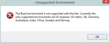
The RISA-Tekla Link currently supports the US Imperial, US Metric for BOTH RISA-3D and RISAConnection.
Additionally the UK, German, Sweden, Norway, China, India, and Australasia environments are supported only for RISAConnection. Below are some details regarding each environment.
Note:

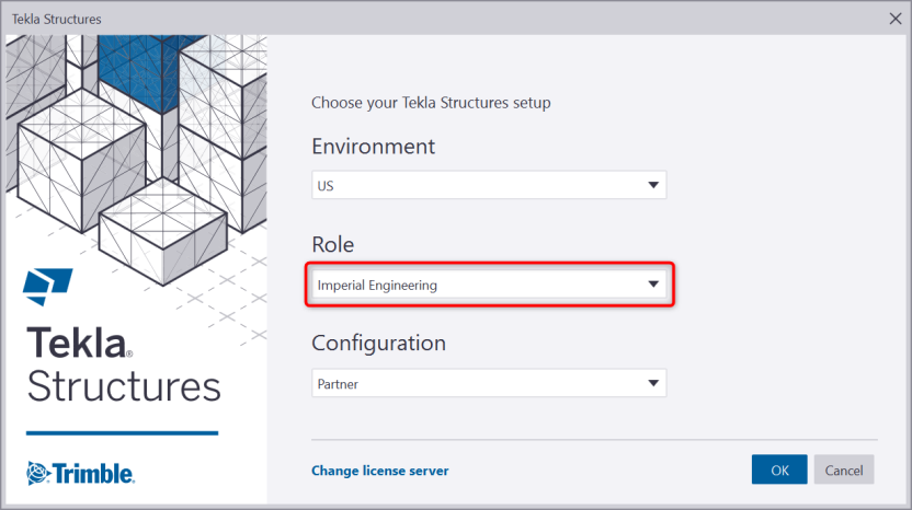
To determine which environment is running the RISA-Tekla Link will look to the TeklaStructuresModel.xml file on either the Environment or the XS_System line.
The RISA-Tekla Link currently supports Imperial Engineering and Metric Engineering for both RISA-3D and RISAConnection.

One of the following operating systems is required:
The following programs and versions required:
The following hardware is required:
The RISA-Tekla Link will let you go from Tekla Structures to RISAConnection Demo. The limitation is that the RISA-Tekla link will not let you transfer back to Tekla Structures to update the Tekla Structures model, or give any results information in Tekla Structures. This does, however, allow you to work with an engineer who owns RISAConnection. For more information on this behavior see the RISA-Tekla Link Integration Procedure topic.
The RISA-Tekla Link will let you work with the RISA-3D Demo. However, the file size, saving and printing limitations from the demonstration version will limit the functionality of the link in demo mode.
For the full license agreement, please visit: risa.com/eula
Complete program support is available to registered owners of RISAConnection. This support is provided for the life of the program. The "life of the program" is defined as the time period for which that version of the program is the current version. In other words. whenever a new version of RISAConnection is released, the life of the previous version is considered to be ended. Technical support is a limited resource; first priority will always be given to those clients who are current on their maintenance.
See Technical Support for a list of your support options.